Amey Sogodekar.

Wheel Assembly Design of a FSAE car
In collaboration with

Role
Design Engineer
Type
Individual
Duration
January 2019 - June 2019
Brief
Acceleracers is the official FSAE team of MITWPU. Objective of this project was to design, manufacture and test Wheel Assembly of ACC 20C (2020 Vehicle)

2020 Vehicle Design Goals
Priority
Reliability
The most important goal was to build a car that would clear all scrutiny tests and successfully complete all dynamic events.
Drivability
Focus was given on
good driver
ergonomics and an
interface that would
allow the driver to
respond quickly to the
feedback received
from car.
Simplicity
With emphasis on
simple design and
part count reduction,
the team aimed at
maximizing time for
testing various
systems and driver
training.
Manufacturability
Designing components
to aid accurate, simple
and fast manufacturing
to maximize testing
time and ensure easily
replaceable parts.
Weight
A target weight of
175kg was set, a 15kg
reduction from the
previous iteration.
Design Concepts
Tool Used: Solidworks 2018

Bearing casing welded to upright
Bearing damaged due to welding contraction
Initial Concept for Wheel Assembly
In the first concept, Mild Steel casing was welded with Mild Steel sheets. But due to welding contraction in casing, the bearings in casing got damaged.
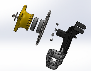
Final Concept for Wheel Assembly
To counter this in next iteration of wheel assembly, a C45 axle was welded to Mild Steel sheets. Bearings were put on this axle which were then press fitted into the Spindle.
Material Selection
Material for Spindle and Upright manufacturing was chosen based on vehicle design goals.
Preferred
Unpreferred
Mild Steel
Aluminium T6 -6061
Aluminium T6 -2014
Reliability
High Fatigue life of components
Manufacturability
Easy to manufacture
Weight
Lower un sprung mass of vehicle
Material Selection Matrix for Spindle and Upright.
The results from selection matrix results led to the choice of Mild Steel for manufacturing Uprights and Aluminum T6 2014 for manufacturing the Spindle.
The brakes team decided on Rotor Material depending on the friction coefficient between the Brake pads and the Rotor.
Rim, Tyre, and Calipers were OEM components. These were reused from the previous vehicle due to budget constraints.
Analysis
Tool Used: Ansys R18.2
As per the DAQ data from last year's vehicle, the vehicle experiences loads of 1.4g Braking, 1.2g Cornering, and 2g Bump. So the upright and spindle were analyzed for these load cases.
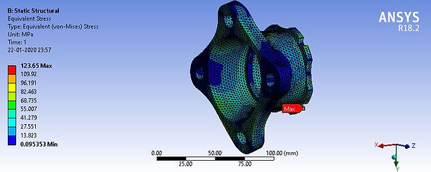
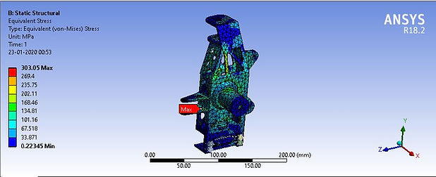
Stress plots for Spindle and Upright
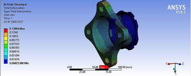
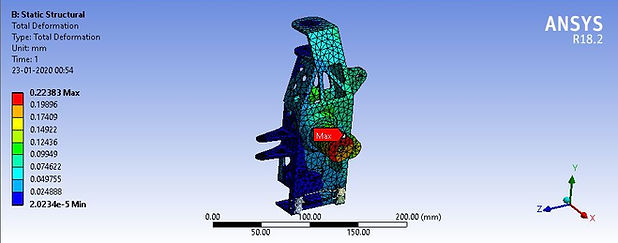
Deformation plots for Spindle and Upright
Manufacturing
The spindles were manufactured from Aluminum T6-2014 billets through precision machining.
The uprights were manufactured by welding together laser-cut Mild Steel components.

Upright Laser Cuts
Mild Steel Welded Upright Challenges
While welding, the geometry of Upright should not change due to welding contraction as it would alter all the suspension parameters of the vehicle.
Solution
Fixtures were used to ensure the axle angle did not change due to welding contraction.
Clamps were used to constrain the motion of Mild Steel Laser cuts due to welding contraction.
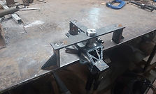


Manufacturing MS Uprights
Final Assembly

